

Cadena Tutorial
This tutorial offers an example-based introduction to the Cadena Development Environment. Before you walk through this tutorial, be sure to read the entire Cadena README file and follow all of the installation instructions.
If you have any questions regarding Cadena or find any errors in this document, please contact cadena@cis.ksu.edu.
Table of Contents
- 1.1 Introduction to Eclipse
- 2.1 Working at the Design Level
- 2.1.1 Creating a Cadena Project
- 2.1.2 Importing Files
- 2.1.3 The IDL3 Editor
- 2.1.4 The Scenario Editor
- 3.1 Code Generation
1.1 Introduction to Eclipse
Eclipse is a Java-based open-source IDE. The Eclipse user interface consists of views and editors grouped together as perspectives. In the figure below, icons representing perspectives are displayed on the far left. The Resource perspective (which will be used throughout this tutorial) is currently selected.
The figure above also shows several views and an editor that will be used in this tutorial. The Navigator view is used for convenient navigation of project files and folders. The Outline view is linked with the editor and displays the hierarchal structure of the edited file. In this example, the editor is also supported by the Tasks view. The Tasks view displays errors and warnings during development.
Perspectives can be switched by selecting a Perspective icon from the bar on the left, or from the menu bar by selecting:
Window—>Open Perspective...
Views can be switched from the menu bar by selecting:
Window—>Show View...
2.1 Working at the Design Level
The Cadena Eclipse plugin provides several additional Eclipse views and editors to facilitate the design and analysis of IDL3 and scenario files. The IDL3 editor supplies an environment to assist with the creation and modification of IDL3 component libraries. The scenario editor provides textual, graphical, and form-based representations of component instances. The textual editor feature of the scenario editor displays the scenario file as text and can verify that component and connection types are correct. The graphical view of the scenario editor generates a visual model of the scenario file, which allows a range of dependency checks to be performed graphically. Finally, the scenario editor's form-based view provides a complete hierarchal representation of the scenario file.
2.1.1 Creating a Cadena Project
To create a new Cadena project:
- Right click within the Navigator view or click on the File menu.
- Select New—>Other... from the popup menu.
- Expand Cadena, click on CCM, and select Cadena CCM Project (as seen above).
- Select "Next".
- Name the new project "BasicSP".
- Select "Next".
- For the CCM Project paths, select "Browse..." and select the directory corresponding to the above path structure. Use the path of the OpenCCM installed during the Cadena installation.
The OpenCCM path should be:
The OpenORB Home path should be:[cadena install]\cadena\OpenCCM-0.6
The C++ Compiler path should be:[cadena install]\cadena\OpenORB-1.3.0[cadena install]\cadena\OpenCCM-0.6\externals\cpp\cpp.exe
Note: The OpenCCM output paths are initialized according to the project name. These paths are passed to OpenCCM during code generation. Leave these paths as they are for now. - Select Finish to create the new project.
If the BasicSP project has been created, it should appear in the Navigator view.
2.1.2 Importing Files
Running the BasicSP example requires the following files to be added to the project:
- basicsp.scenario
- common.cps
- common.idl3
Files of type ".scenario" need to be imported into system\cad\, files of type ".cps" need to be imported into system\cps\, and files of type ".idl3" need to be imported into system\idl\.
To import common.idl3 and common.cps:
- In the Navigator View, expand all folders.
- Select the "system" folder.
- Click the right mouse button, Select "Import..."
- Select "File system" as the import source.
- Select "Next".
- For the directory, select "[cadena installation]\example-files\common".
- Select "common.idl3" and "common.cps" as seen in the figure above.
- Select "Finish" to import the selected files.
The Navigator provides support for drag and drop file moves. By dragging and dropping files within the Navigator view, project files can be sorted quickly.
- In the Navigator view, expand the "BasicSP\system" folder.
- Drag common.cps and drop it in "BasicSP\system\cps".
- Drag common.idl3 and drop it in "BasicSP\system\idl".
The Navigator view should now resemble the following figure:
Importing the basicsp.scenario file is done similarly. To import basicsp.scenario:
- In the Navigator View, expand all folders.
- Select the "BasicSP\system\cad" folder.
- Click the right mouse button, Select "Import..."
- Select "File system" as the import source.
- Select "Next".
- For the directory, select "[cadena installation]\example-files\basicsp".
Note: If working in Linux, Eclipse doesn't always clear the text area when you switch directories, so you may have to delete text if it appears in the text area.
- Select "basicsp.scenario".
- Select "Finish" to import the selected file.
The Navigator view in the following figure illustrates a project that is set up correctly.
2.1.3 The IDL3 Editor
The IDL3 editor is used to edit and compile IDL3 files. IDL3 files are compiled using OpenCCM. OpenCCM is an open-source compilation and generation tool for CORBA component model specifications. Additional OpenCCM information is available from http://www.objectweb.org/openccm/.
OpenCCM utilizes an Interface Repository (IR) to compile the IDL3 files. The IR must be started before the IDL3 files can be compiled. To load common.idl3 into the IR:
- Open "common.idl3".
- Make sure the focus is on the common.idl3 file editor.
- Select IR—>Start Interface Repository from the menu bar.
- Make sure the focus is on the common.idl3 file editor.
- Select IR—>Compile Current IDL3 File from the menu bar.
The required IDL3 file for basicsp.scenario has been compiled into the IR. Also, the OpenCCM Console view has now been been added to the perspective. The OpenCCM Console view supplies feedback about the status of IDL3 file compilations into the IR.
Note: It is usually a good idea to stop the IR and close the scenario and CPS files before exiting Eclipse. If an IDL3 compile error occurs (or some other error that is related to the IR), it is generally a good idea to stop the IR, then start it back up again. Remember that IDL3 files must be compiled into the IR again whenever the IR is restarted.
2.1.4 The Scenario Editor
If the IDL3 file has been properly compiled, the scenario editor can be opened by double-clicking on basicsp.scenario in the Navigator view. The scenario editor consists of three tabbed views representing the same scenario. These three tabbed panes provide textual, graphical, and form-based representations of the scenario. When a scenario is changed in one pane, the other two panes are updated to reflect any changes.
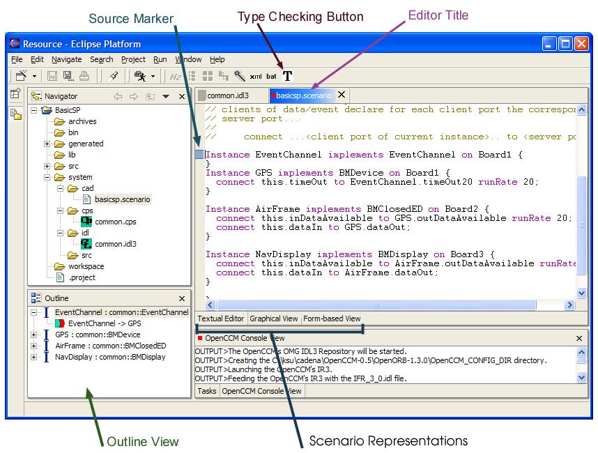
2.1.4.1 Textual Editor
The textual editor displays the scenario file in text form. When editing the scenario from the textual editor pane, the type checking button is enabled. Selecting this button will type check the scenario and display any errors in the task view. If the task view is not shown, it may be opened with:
Window—>Show View—>Other—>Basic—>Tasks
The scenario editor depends on the IDL3 editor because IDL3 and CPS files define the components that are used in scenario files. Scenario files must import these components using the "importLib" keyword. The following excerpt of basicsp.scenario (visible in the textual view) contains two import statements.
system BasicScenario {

  importLib common.*;
  importCPS common;

  Rates 20;

  Locations Board1, Board2, Board3;

  Instance EventChannel implements EventChannel on Board1 {
  }
  .
  .
  .
Scenario files use an import convention similar to what is used by the Java programming language. The excerpt above imports all components from the "common" module, so the IDL3 file defining the common module must be loaded into the OpenCCM repository. In this case the required IDL3 file is common.idl3.
For more information on editing scenario files in their text form, click here.
2.1.4.2 Graphical View
The graphical view presents the scenario file as a diagram of components connected through either event or data connections. This view also allows the user to query the model on several different levels. For example, to check the scenario for cycles:
- From the graphical view, right click a component.
- Select "Cycle check".
- A cycle should NOT be detected.
To reset the graphical view:
- In the graphical view, right click anywhere.
- Select "Reset".
When using the graphical view, the outline view displays the complete graphical workspace so that it is easier to maneuver if the project has many components and connections. The graphical view also has a zoom feature, which can be used by right-clicking within the editor window and selecting a percentage. Also, any one of the scenario editor representations can be maximized by double-clicking the editor title.
Now try a forward port-level slice:
- Right click the GPS component.
- Select "Forward port-level slice".
- Select "outDataAvailable".
- Select "OK".
All ports and components downstream of GPS.outDataAvailable have been highlighted. We can follow the forward port-level slice from GPS.outDataAvailable to NavDisplay.dataIn by examining the scenario file in the textual editor. The numbers in the figure below show which connections are affected by this forward port-level slice.
Backward slicing, the reverse notion of forward slicing, is also supported by the graphical view. While forward slicing calculates all ports that are affected by a given port, backward slicing calculates all ports that may affect the given port. The following figure illustrates the result of performing a backward slice from the EventChannel component.
The last feature in this section is "chopping". Once a pair of ports have been designated as the starting and ending points, chopping will provide the set of ports that occur along the path between this given pair of ports.
To chop:
- Right click the GPS component.
- Select "Pick chop start".
- Select "outDataAvailable".
- Select "OK".
- Right click the NavDisplay component.
- Select "Pick chop end".
- Select "inDataAvailable".
- Select "OK".
- Right click within the graphical view.
- Select "Chop".
The following figure should mirror the result
The dependencies between ports of different instances of components is obvious via connections between them. However, information such as the outputs triggered by an input port in a particular mode is not obvious. These kinds of intracomponent dependencies are specified in Cadena Properties Specification (CPS) files. The details of this file type are not required at this point (click here for more information on CPS files). Instead, it is sufficient to know that the dependency analysis features use the information contained in CPS files. If CPS files are not available during the analysis, then a worst-case assumption is made. This worst-case assumption is that any input port can trigger all output ports.
2.1.4.3 Form-based View
In the form-based representation of the scenario, information about components and connections is presented as a table (spreadsheet). All of the connections that each component maintains are displayed in this view, whereas the textual editor displays a connection under only one of the components.
Unlike the graphical representation (which is just a view), this representation of the scenario is a full-fledged editor. Components and connections can be added and/or deleted in the form-based view. It is possible to add imports, too. The connections appear as children in a tree routed below a component. To toggle the expansion of all nodes in the table, click on the "Toggle branch expansion" button in the toolbar.
Upon adding a connection, the unspecified end of the connection is defaulted. This connection can be edited by focussing on the connection in the "Component/Port" column and double-clicking in the "Connected to" column in the same row. All ports to which the given port may possibly be connected to will appear. After a new port has been selected, hitting "return" will confirm the change. Likewise, the "Delivery method" associated with a non-data connection can be changed.
Each component is associated with a location. This can be edited by double-clicking in the "Location" column after focussing on the row of interest. Upon entering a valid location and pressing "return", the model is updated. If the location did not exist in the model, then it is added to the model. Similar actions can be performed to set the rates associated with connections.
Note: Changes made to import statements, rates, and locations (in the form-based view or textual editor) are not visible in the graphical view, but do occur.
The form-based view is also equipped with 3 additional features that are not available in any other representation. These features include the ability to automate the seeding of rates, distribute components, and detect remote event deliveries that can be converted into local dispatches. These features are described in the following paragraphs.
RATE SEEDING - It is possible to have a system where a port deals with connections that have differing rates. These connections and all connections affected by such connections are highlighted in RED color. Conflicts of this type can be easily resolved by using the automatic rate seeding feature. This feature can be invoked by clicking the "Seed rates" button in the toolbar. The tool will seed rates in a rate monotonic fashion. For this to work successfully, however, the connections involving trigger ports in the system should have their rates specified.
DISTRIBUTION OF COMPONENTS - In the form-based view, it is possbile to assign locations to a few components, then ask the tool to distribute the unassigned components among the available locations. This is accomplished by clicking the "Distribute the components" button in the toolbar. Note that the distribution will be better when there are fewer connections that have non-zero rates. The reason for this is that the distribution algorithm will try to minimize the inter-location traffic.
FINDING ERM CONNECTIONS - The third feature detects remote event deliveries between collocated components into local dispatches. This feature is available by clicking the "Find ERM connections" button in the toolbar. All connections on which event dispatches can be converted into local dispatches are highlighted in GREEN color. Again, this feature works best after automated distribution.
The figure above illustrates the result of seeding rates, distributing the components, and finding ERM connections.
3.1 Code Generation
Once a scenario has been loaded and all required IDL3 files (only one for this example) have been compiled into the Interface Repository, Cadena can generate source and build scripts. Cadena uses OpenCCM to produce most of the Java code, while it creates the Boeing XML and the build scripts entirely on its own. The following sections continue to use the BasicSP example.
3.1.1 Generating Java Code (Stubs, Skeletons and Implementations)
The stubs, skeletons and implementations for the current project can be generated automatically by Cadena. Click the magic wand in the menu bar to generate all of the associated Java files.
The generated files are placed in different locations depending on what kind of file they are. As seen in the figure above, stubs are placed within "BasicSP\generated\stubs", skeletons are placed within "BasicSP\generated\skeletons", and the implementations are placed within "BasicSP\src".
Note: To refresh the Navigator view, right-click on the project name (in the Navigator view), then select "Refresh".
Business logic may now be inserted into the monolithic implementation code that was just generated. Before the business logic can be applied, however, the home implementation code that was also generated must be modified. That is because the home implementation code manages the components and creates the monolithic implementations. Inside each home implementation, a create method must return a monolithic implementation. The following figures show the modification of the home implementation file for the BMDevice component.
  //
  //  IDL:cadena/common/CCM_BMDeviceHomeImplicitcreate:1.0
  //
  /**
   **  Implementation of the ::common::CCM_BMDeviceHomeImplicit::create operation.
   **/
  public org.omg.Components.EnterpriseComponent
  create()
  throws org.omg.Components.CCMException
  {
      //
      //  TODO : implement
      //
      return null;
  }
By default, this method returns null. This needs to be modified as follows:
  //
  //  IDL:cadena/common/CCM_BMDeviceHomeImplicitcreate:1.0
  //
  /**
   **  Implementation of the ::common::CCM_BMDeviceHomeImplicit::create operation.
   **/
  public org.omg.Components.EnterpriseComponent
  create()
  throws org.omg.Components.CCMException
  {
      //
      //  TODO : implement
      //
      return new BMDeviceMonolithicImpl();
  }
This kind of modification needs to be made to all of the home implementation files.
3.1.2 Generating Boeing OEP XML
In addition to generating Java code, Cadena can also generate Boeing XML code that can be used with OEP build v2.2. To generate the XML code, it is necessary to define a "toDisplayNames.properties" file in the "BasicSP\system\src" directory. This can only be done after the IDL3 and scenario files have been written. The toDisplayNames.properties file is used to get the information that is not included in the scenario file. The toDisplayNames.properties file has already been written for the BasicSP example.
To import toDisplayNames.properties:
- In the Navigator view, select the "BasicSP\system\src" folder.
- Click the right mouse button, Select "Import..."
- Select "File system" as the import source.
- Select "Next".
- For the directory, select "[cadena installation]\example-files\basicsp".
- Select "toDisplayNames.properties".
- Select "Finish" to import the selected file.
The property file provides three functionalities. First, it provides display information for component homes and component instances. Since the scenario file usually uses different instance/component names than the Boeing OEP XML, scenario names must be mapped to the Boeing OEP XML names. This functionality is accomplished within the "toDisplayNames.properties" file. For example, if a component instance is named "DataSource" in the scenario file, and we want to display it as "DATA_SOURCE" in the Boeing OEP XML file, then the property for "DataSource" in "toDisplayNames.properties" should appear as: DataSource = DATA_SOURCE.
    mode = basicsp
    BMClosedED = BM__CLOSED_ED_COMPONENT
    BMDevice = BM__DEVICE_COMPONENT
    BMDisplay = BM__DISPLAY_COMPONENT
    GPS = GPS
    AirFrame = AIRFRAME
    NavDisplay = NAV_DISPLAY
    EventChannel_EventChannel = EventChannel
    GPS_BMDevice = BMDevice
    AirFrame_BMClosedED = BMClosedED
    NavDisplay_BMDisplay = BMDisplay
Figure 3.4. The toDisplayNames.properties file for the BasicSP example.
Secondly, the "toDisplayNames.properties" file provides some implementation information for component instances. In the current CCM translation of OEP scenarios, one component in OEP may correspond to multiple components defined in the IDL3 file because of a different number of ports. We combine the component instance name and component type name from the scenario file as the key, and we set the corresponding component name in OEP as the value. For example, there may be an instance named "GPS" in the scenario file which implements component type "Device". If "GPS" implements component type "BMDevice" in the OEP XML file, then the property for "GPS" should be written as: GPS_Device = BMDevice.
The third use for the "toDisplayNames.properties" file is to indicate which level of information is being specified. This is done by setting the model property. The model property indicates whether the model is MediumSP, ModalSP, or BasicSP. For example, the entry "model = BasicSP" would indicate the use of the BasicSP model.
After a "toDisplayNames.properties" file has been added to the project in the "BasicSP\system\src" directory, an OEP XML file may be generated by clicking the "Generate OEP XML" button (indicated in figure 3.1). The OEP XML will be generated within the "BasicSP\generated" directory. For the newly generated XML to show up in the Navigator view, it may be necessary to refresh the project.
3.1.3 Generating Build Scripts
The correct scripts must be generated to compile and run the project. This is triggered by pressing the "generate build and run scripts" menu button (see figure 3.1). The run scripts can be found in the "bin" directory, and the build scripts are placed in the BasicSP (project) directory.
3.1.4 Compiling and Running
Once the business logic has been implemented within the monolithic implementations and build scripts have been generated, then the project can be compiled from a separate command window. Go to the IDL3 editor and stop the IR before completing the following steps:
- Open a command prompt window and change directory to the cadena installation.
- Cadena environment needs to be setup in order to compile the project. For this, type the following at the prompt
"OpenCCM-0.6\OpenORB-1.3.0\bin\envi_OpenCCM.bat" (for Windows), or
". OpenCCM-0.6/OpenORB-1.3.0/bin/envi.OpenCCM.sh" (for Linux). - Now change the directory to the eclipse workspace. This is the 'workspace' directory under the eclipse installation that comes with cadena.
- The project created using cadena will be listed in this directory. Change the directory to the project that has to be compiled.
- Type "build" ("build.sh" for Linux) at the commmand prompt.
- Once the build is successful, the implementations can be run using the scripts generated.
To run the project, type "bin\start_java" ("bin/start_java.sh" for Linux) at the command prompt. This goes through the general process of starting the component servers and the name service before running the project itself. The execution of the project can be terminated by running the "bin\stop_java" script ("bin/stop_java.sh" for Linux). These scripts must be run from the [Cadena installation]\eclipse\workspace\BasicSP directory.